UR5e Gomoku Player
Introduction
For my Robotics(MTRN4230) course at UNSW, we were working with UR5e manipulators to learn more about Forward and Inverse Kinematics in manipulator arms and program simple tasks such as writing words on sheets of paper. For the group project component of the course, we were required to demonstrate an application using the UR5e and simulate it in Gazebo using ROS1(Melodic) before attempting to recreating it in the lab using real robots. While the latter part of this was eventually dropped(due to COVID lab restrictions), our final demo could theoretically be done in the lab given adequate time to test.
After brainstorming ideas as a group, we eventually decided to go forward with making a robot opponent that could play 5-in-a-row against a human opponent given a real board and pieces. This scenario offered the ideal level of complexity considering the fact that it was the first exposure to ROS for most of us. The associated props also had simple geometries which meant we could spend more time on figuring out how to move the robot instead of creating assets on blender1.
Assets
The ROS packages for the UR5e robot were obtained from ROS-Industrial Universal Robot Meta-Package which consisted of the URDFs, mesh files, moveit_configs, kinematics configs etc. In addition, it was also mandatory to use the Robotiq E-Pick vacuum gripper. Since this end effector was not part of the default configs of the UR5e(things like the kinematics and moveit), new ones needed to be generated.
ROS Nodes
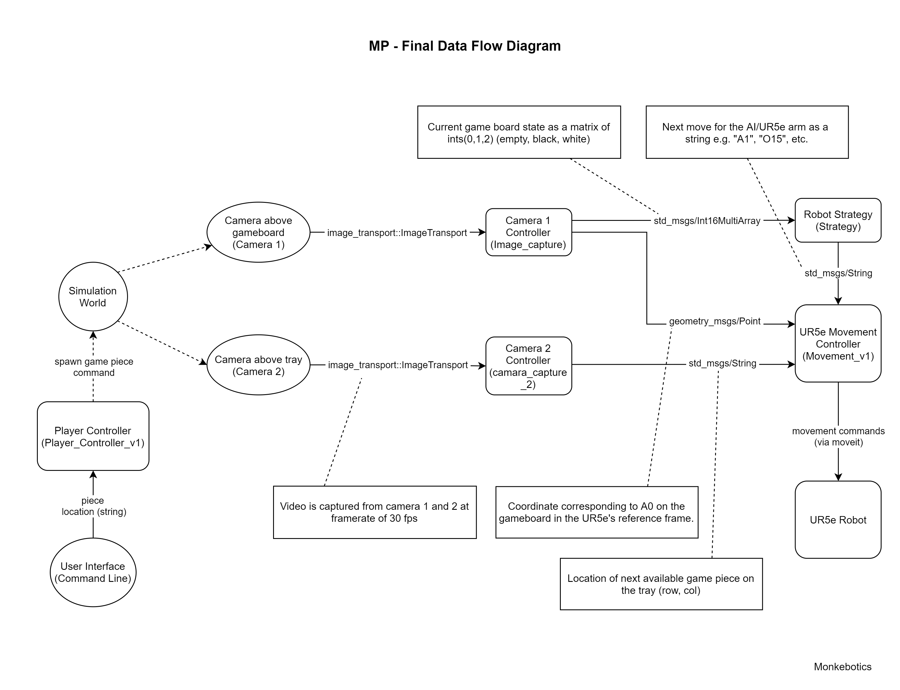
The final demo consisted of 5 ROS nodes, each performing a particular task.
- Player Controller:
- Camera Node 1: takes in an image of the game board and outputs in current state and a reference location(A0).
- Camera Node 2: takes in an image of the pieces tray and outputs the location of the next piece to pick up.
- Robot Strategy/AI: takes in the current state of the board and outputs the coordinates for the next move.
- UR5e Movement Controller:
Overview

Vision
For the simulation, there were 2 cameras that were set up - 1 located above the game board(camera 1) and another over the tray containing the pieces(camera 2).
Strategy/AI2
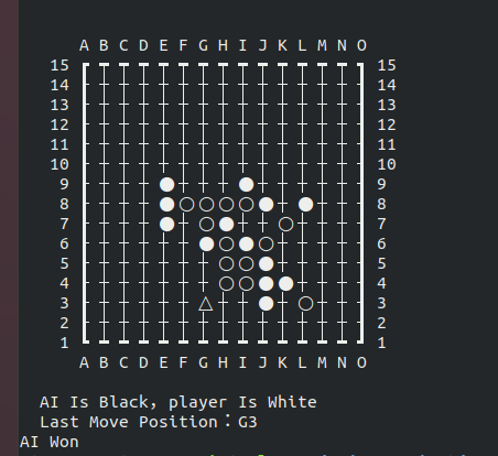
The robot simply used a MinMax based strategy to play.

T.B.C
Footnotes
-
We could’ve just downloaded models from somewhere like grabcad but we decided against this since (a) the geometries were quite simple, (b) we may have had to deal with issues like cleaning the models or licensing, and (c) making the props ourselves may have been a part of the course (can’t recall 🤔). ↩
-
No, there’s nothing too fancy here. ↩